Machine Design: Button Presser-Four Bar Linkage
Project Overview: The goal of this project is to design, build, and test a powered mechanism that will automatically press arcade buttons on a playing field as rapidly as possible. The goal is to press the blue, red, and yellow buttons as many times as possible in 1 minute. The device developed moved to each of the buttons, and pressed them. It used a DC electric motor in a closed loop position control system to move the button-pressing mechanism to the desired position and orientation accurately enough to press the buttons, and quickly enough to press as many as possible.
My Role: Mechanical Engineer (Team of 5)
Work in a team of 5 to create a electro-mechanical four bar linkage system. I specifically worked on the design and manufacturing portion of the project.

Design
- Solidworks
- Sketching
- CAD
- Simulation
- Fusion 360
- Coupler Design
- CAM
- Linkage Assembly
Manufacturing
- Rapid Prototyping
- 3D printing (FDM/SLA)
- Laser Cutting
- CNC Machining
- Tormach Mill/Lathe
- Fryer Mill/Lathe
- Manual Machining
- Drill/Arbor Press
- Horizontal/Vertical Bandsaw
Deliverables
- Electro-mechanical Button-Pushing Linkage System
- Final Project Report
Key Outcomes: 1. Pressed 72 buttons in one minute 2. Used unique CAM follower button pressing mechanism
Engineering and Design Process:
Simulating Linkage Formation and Transmission Angle:
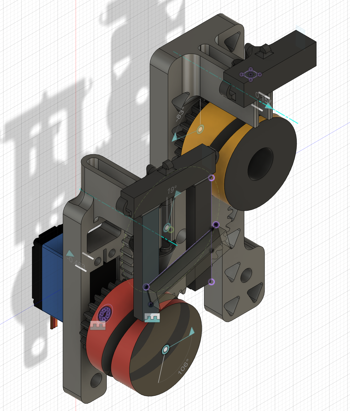
I employed a graphical construction approach utilizing SolidWorks’ Sketch Blocks feature to design a 2D layout of a versatile linkage mechanism. This design allows for easy modifications to explore various configurations. The mechanism is designed to press three mandatory button pairs on a playing field, with the option to include a fourth bonus button. Additionally, the design ensures compliance with critical criteria, such as feasible ground pivot positions and acceptable transmission angles. The linkage chosen for my team’s linkage has transmission angles: 43.37°, 80.37°, 95.93°. This linkage design was chosen for its efficiency and versatility. It achieves one of the smallest volumes at the three button positions, maximizing points in the prototype volume category. The transmission angles fall within the ideal 30-150 degree range, with minimal deviation from 90 degrees, ensuring strong performance in the rubric’s criteria. Additionally, the design avoids linkage crossover, simplifying assembly by allowing links to be bolted on one or alternating sides of the ground plate. The alignment of link ends with the ground plate holes and the larger coupler size further enhance stability and flexibility in the design.


Coupler Design:
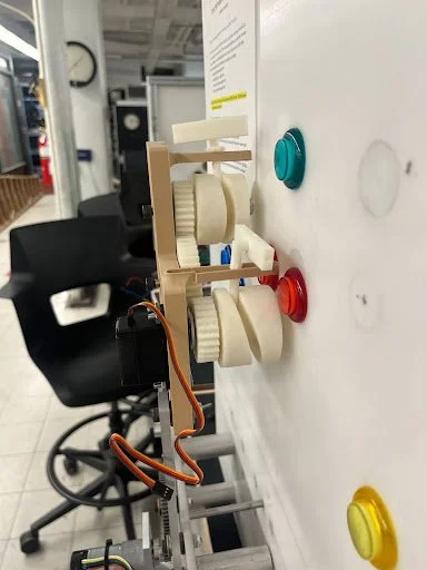
Our coupler link were joined via oil bearings and shoulder set screws to our driver and follower linkages. These oil bearings were press fitted into the holes to ensure a tight fit. A DC servo motor was used as our actuator. This motor was then attached to a cam shaft that translates provided rotational motion to linear motion in order to press buttons. The motor was attached to the coupler link using screws and bolts to support the camshaft mechanism. Support links were added for additional support as the camshaft moves, to prevent vibration-induced errors. The cam-shaft mechanism was attached to the coupler via nuts and thrust bearings with polished dowels. The cam followers and DC motor have gears attached to them that allows one motor to actuate both button pressers.

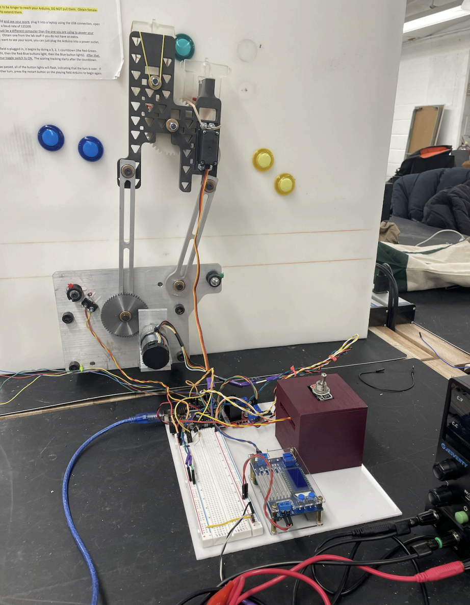
Machining and Assembly:
The parts were manufactured in the mechanical engineering machine shop. The links and ground plate were water jetted and then reamed/drilled for oil sleeve bearings that were press fitted into the holes using an arbor press. The spacers and hard stops were made on the Fryer lathe using the parting tool. The coupler/button-pushing mechanism was iterated over using SLA and SLS 3D printing. The L-Bracket was machined using the bandsaw and the CNC Tormach mill using CAM generated on Fusion 360. Dowel pins secured the assembly to the playing field (white back board holding the LED buttons).